Here you can read the latest news from Fumex.
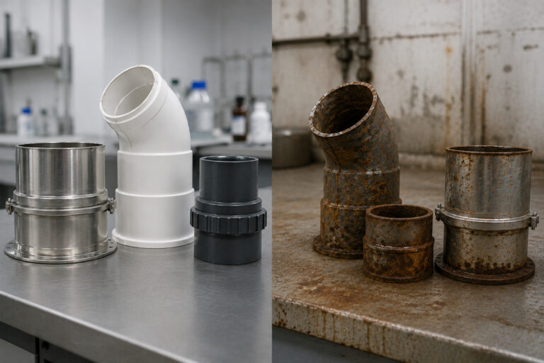
Materials Matter: Choosing Extraction Equipment for Different Laboratory Processes
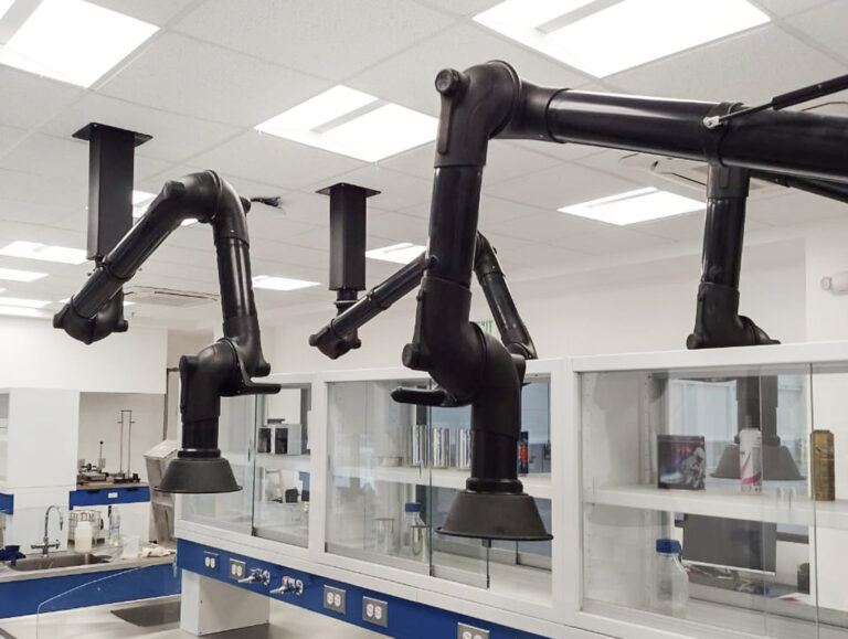
5 Common Design Mistakes in Laboratory Extraction Systems

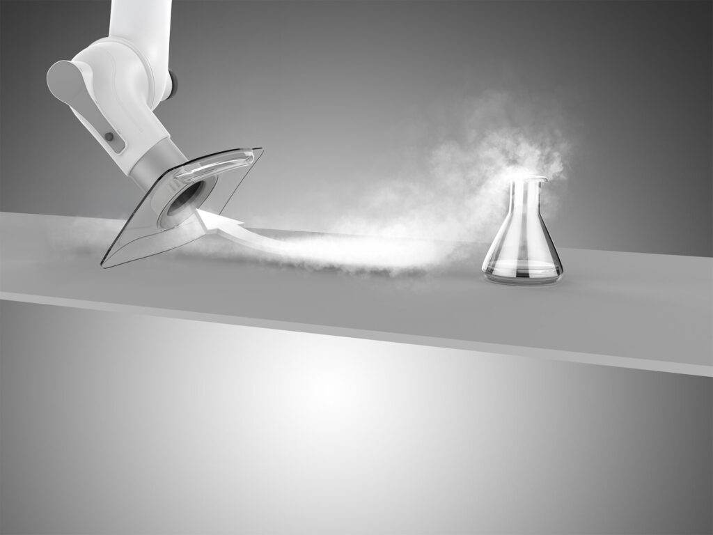
Capture Performance: Why Airflow Alone Does Not Determine Effective Extraction

How to Select the Right Extraction Arm for Your Laboratory

“A little better every day” – Anders Hedlund reflects on his journey with Fumex

Meet Movex at I2SL 2026 in Boston – Booth 311

What EX means — and why it matters in extraction

Why you need industrial source extraction
Why material selection matters in corrosive environments
Source Extraction in Laboratories: Precision Where It Matters

Opening hours during the summer

New at Fumex GmbH – Jeaneth is already an important part of the team
When the right expertise meets the right idea: the Fumex augmented reality app

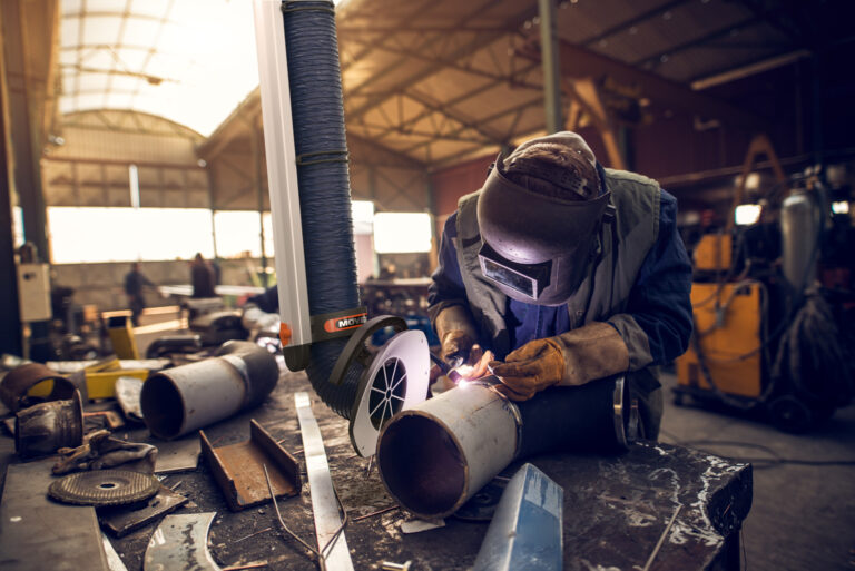
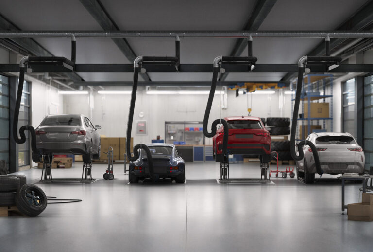
Why local extraction is essential for vehicle exhaust and welding fumes
Welcome to the open house on Saturday, November 9

Jussi Minkkinen is Fumex’s new Production Manager – “I am driven by continuous improvement”

Japanese Dalton visits Fumex – focus on future cooperation
Introducing Mike Murphy – Movex’s new National Sales Manager

Opening ceremony for our new headquarters – See the pictures from the event!

Introducing Kenny Stenberg – ISO Coordinator at our parent company Fumex

Increasing the knowledge of environmental and social sustainability

Anders Hedlund takes the floor – “Trust me, there is a lot going on at Movex!”
PRX – An effective “heavy duty” extraction arm
CV – Modular filter for both particles and gas
Pressure Drop and Energy Use in Laboratory Extraction Systems
When designing a laboratory extraction system, it is easy to focus on one number: airflow. How many CFM does the extraction point need?
That is an important question — but it is only half of the equation. The fan must not only move the required volume of air. It must also overcome the resistance created by the extraction arm, ductwork, bends, dampers and every other component in the airflow path.
That resistance is measured as pressure drop.
Understanding it is essential when selecting extraction equipment, sizing the fan and designing a system that uses energy efficiently.
What is pressure drop?
As air moves through an extraction system, it encounters resistance. Friction against duct surfaces creates resistance. So do bends, transitions, dampers, extraction arms and other components that change the direction or velocity of the airflow.
In U.S. ventilation systems, static pressure is commonly expressed in inches of water gauge (in.wg.).
A component with a low pressure drop creates relatively little resistance. A component with a high pressure drop requires the fan to generate more pressure to maintain the same airflow.
The important point is that these losses add together.
The extraction arm may represent only one part of the total pressure requirement. The complete system must be considered from the capture point all the way to the exhaust.
Why pressure drop affects energy use
A fan creates both airflow and pressure. If two systems need the same airflow, but one has substantially more resistance, the fan in the higher-resistance system must do more work to maintain that airflow.
In simple terms, the air power required by a fan is related to:
Airflow × pressure
Fan and motor efficiencies then determine how much electrical power is required to produce that air power.
This is why reducing unnecessary system resistance can have an impact on operating cost. The U.S. Department of Energy also identifies duct configuration, pressure losses and fan operating point as important factors in fan-system efficiency.
It also explains why simply installing a larger fan is not the best way to solve a poorly designed system.
The extraction arm is part of the pressure calculation
The extraction arm is the first component in the airflow path, and its internal design can make a significant difference.
Joints, internal support structures and changes in cross-sectional area can obstruct the airflow and create turbulence.
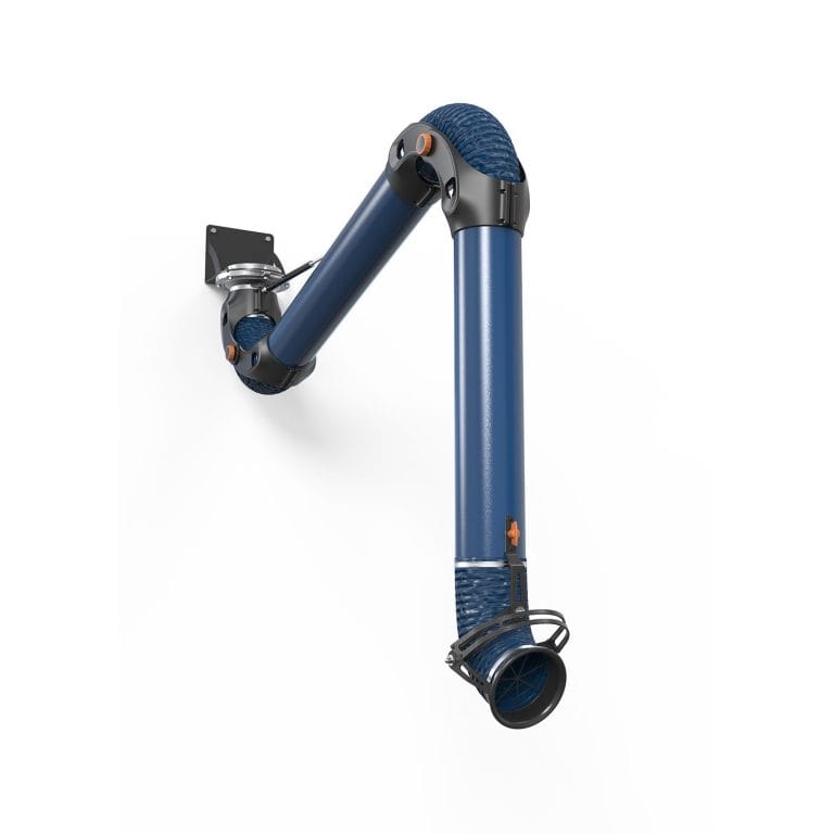
Our ME extraction arm is designed around a low-resistance airflow path while still providing the flexibility and positional stability required at a laboratory workstation.
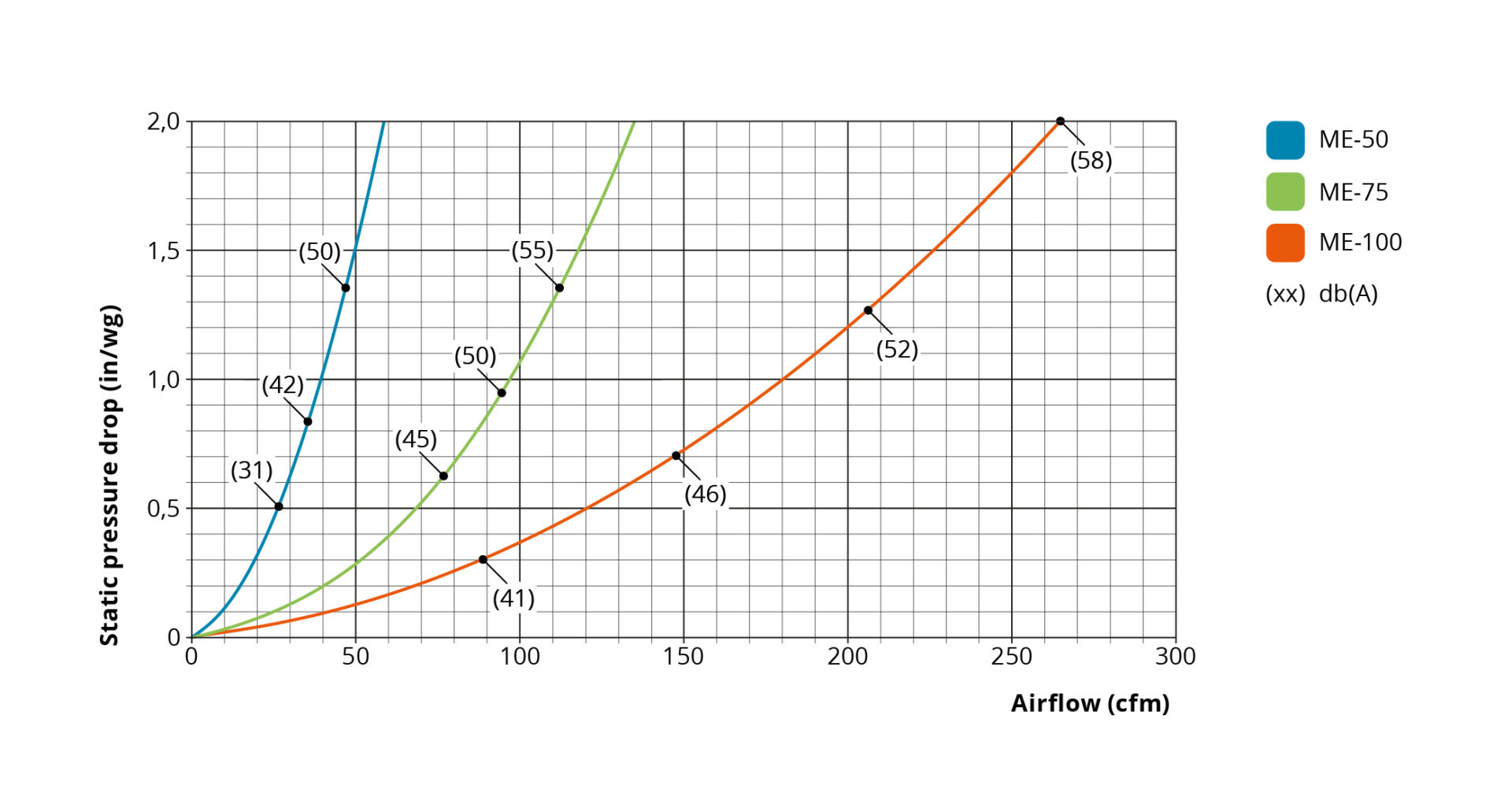
ME is available in three diameters, and pressure drop increases as airflow through each size increases.
 Diameter and airflow need to work together
The pressure-drop curves also illustrate why extraction-arm diameter matters.
For laboratory applications, we recommend the following airflow ranges for the ME series:
| Model | Diameter | Recommended laboratory airflow |
|---|---|---|
| ME 50 | 2 in. | 30–45 CFM |
| ME 75 | 3 in. | 70–85 CFM |
| ME 100 | 4 in. | 120–180 CFM |
A smaller diameter can be appropriate when the required airflow is low and the extraction point can be positioned close to the source.
When a process requires substantially more airflow, increasing the diameter allows that airflow to be transported without forcing air through an unnecessarily restrictive opening.
This is why simply increasing fan speed is not always the right response when more airflow is needed.
The extraction arm, ductwork and fan need to be considered together.
MiniTEX: another example of low-resistance design
MiniTEX uses a telescopic design with a relatively clear internal airflow path.
There are no internal support arms obstructing the airstream, helping keep resistance low while maintaining a compact working radius.
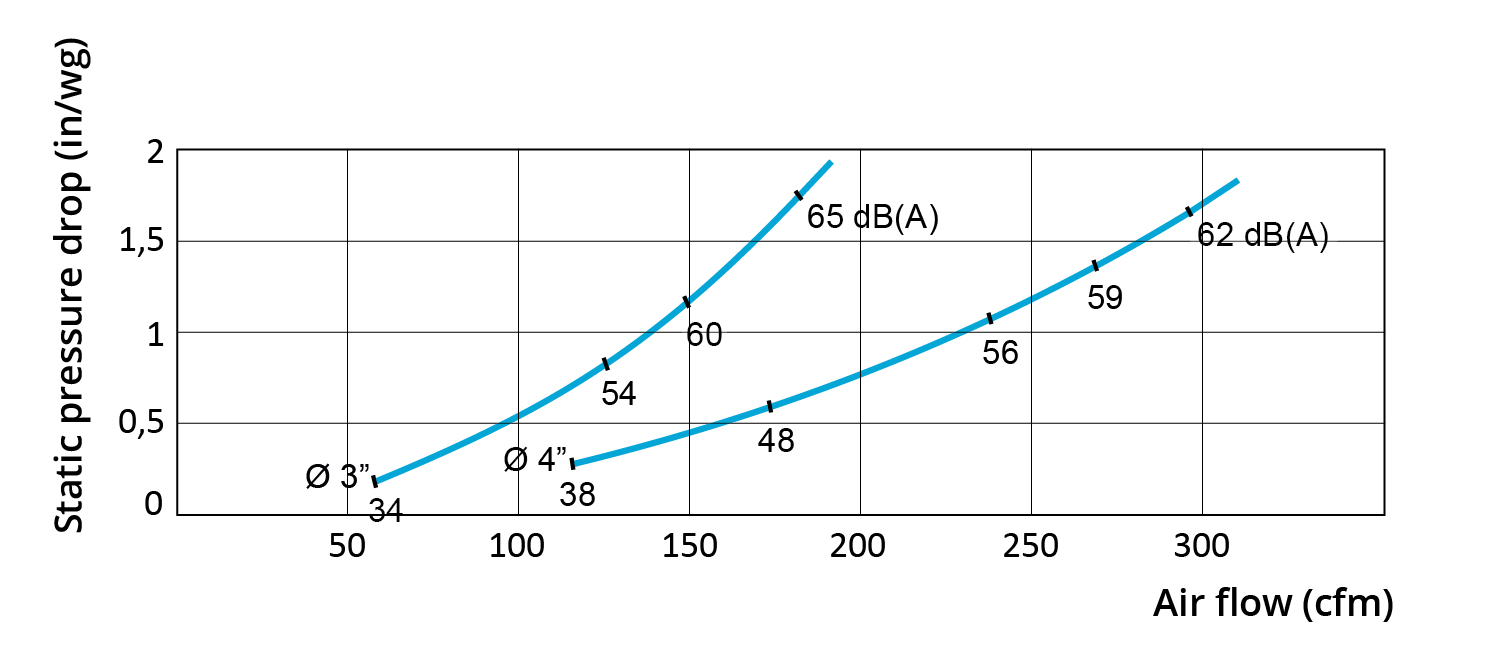
For most laboratory applications, a 3 in. MiniTEX operating at approximately 80 CFM provides a good balance of airflow, compact size and low pressure drop.
At that operating point, the product data shows a static pressure drop of approximately 0.5 in.wg.
The duct system can create even more resistance
A low-pressure-drop extraction arm cannot compensate for an unnecessarily restrictive duct system.
Duct diameter, total length, bends, transitions and branch connections all influence resistance.
Sharp bends and poor airflow conditions can also create additional losses. AMCA describes these installation-related losses as system effects and notes that they can reduce fan-system performance, increase energy use and contribute to additional noise.
The objective should therefore be to create a direct and efficient airflow path wherever the building layout allows.
That does not simply mean making every duct as large as possible. Duct sizing must still consider the required airflow and the characteristics of the contaminant being transported.
The important principle is to avoid resistance that does not serve a purpose.
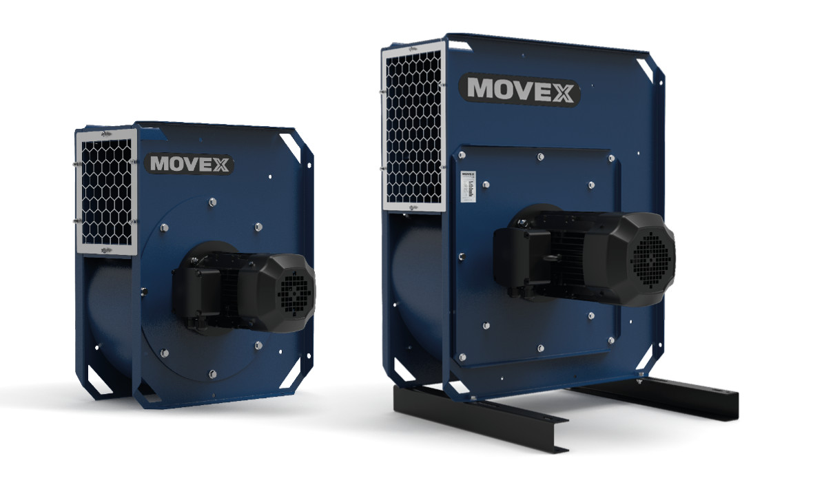
More fan is not always the solution
When an installed system does not provide enough airflow, increasing fan speed or installing a larger fan can appear to be the easiest solution.
But if the real problem is excessive system resistance, the fan is being asked to compensate for the design.
That can mean higher energy consumption and increased noise without addressing the underlying issue.
Fan selection should instead be based on an operating point that combines:
Required airflow + total system pressure
The fan curve can then be used to determine whether the selected fan can provide the required CFM at that pressure.
This is why pressure-drop data for extraction arms and other system components is important during the design stage.
Multi-point laboratories create another challenge
Laboratories often have several extraction points connected to a common duct system.
The maximum system demand may occur when many extraction points are being used simultaneously.
But that does not necessarily represent normal operation.
If eight extraction arms are installed and only three are being used, the airflow requirement of the system may be very different from when all eight are operating.
Opening and closing dampers also changes the resistance and pressure conditions within the duct system.
This is where fan control becomes important.
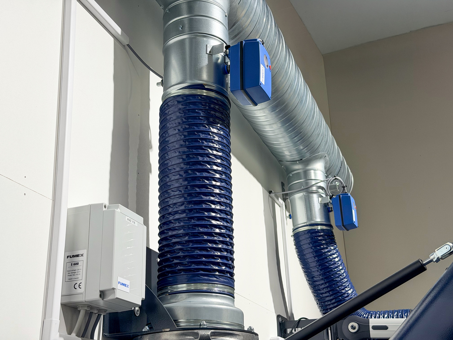
Adjust fan operation to actual demand
Instead of operating the fan continuously for maximum system demand, variable-speed control can allow the system to react to changing conditions.
Our automatic control system can combine an SFC frequency converter with an ST 300 pressure transmitter.
The pressure transmitter measures conditions in the main duct and the frequency converter regulates fan speed to maintain the set pressure as system demand changes.
This is particularly useful when several extraction points share the same fan.
When fewer extraction points require airflow, the fan does not necessarily need to operate at the same speed required for maximum demand.
The U.S. Department of Energy similarly identifies variable-speed control as an important energy-performance measure for fan systems where airflow demand varies.
Low resistance matters throughout the system
Efficient laboratory extraction is not created by one low-pressure-drop component.
It comes from considering the complete airflow path.
Start with the airflow required to capture the contaminant. Select an extraction arm that can provide that airflow efficiently. Design the ductwork to avoid unnecessary resistance. Calculate the total system pressure and select the fan for the resulting operating point.
For systems where demand changes, consider whether fan control can allow the system to respond dynamically.
The result is a system designed to provide the airflow that is actually needed — without asking the fan to overcome unnecessary resistance.
Interested in Movex solutions?
We can help you with the right equipment for your laboratory.