Here you can read the latest news from Fumex.
Materials Matter: Choosing Extraction Equipment for Different Laboratory Processes
Capture Performance: Why Airflow Alone Does Not Determine Effective Extraction

Pressure Drop and Energy Use in Laboratory Extraction Systems
How to Select the Right Extraction Arm for Your Laboratory

“A little better every day” – Anders Hedlund reflects on his journey with Fumex

Meet Movex at I2SL 2026 in Boston – Booth 311

What EX means — and why it matters in extraction

Why you need industrial source extraction
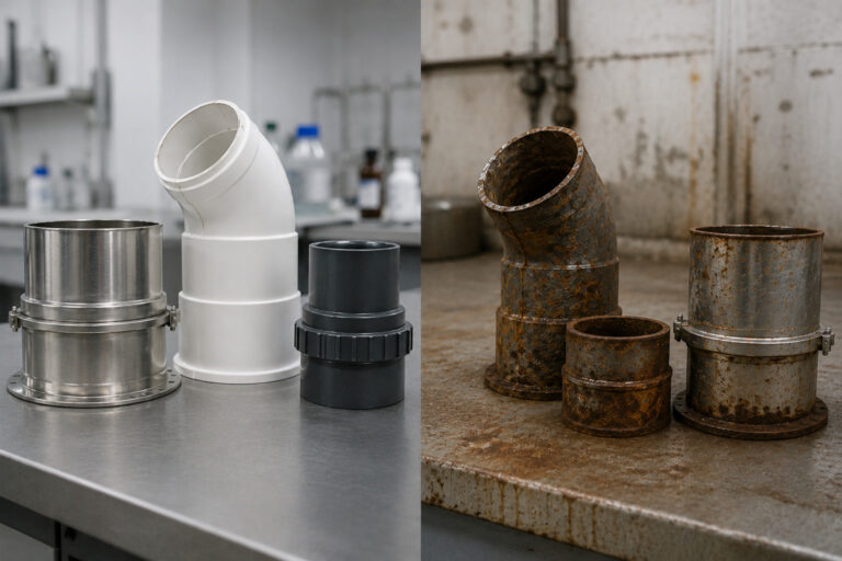
Why material selection matters in corrosive environments
Source Extraction in Laboratories: Precision Where It Matters

Opening hours during the summer

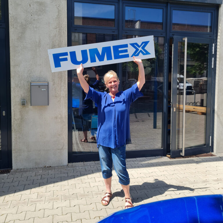
New at Fumex GmbH – Jeaneth is already an important part of the team
When the right expertise meets the right idea: the Fumex augmented reality app

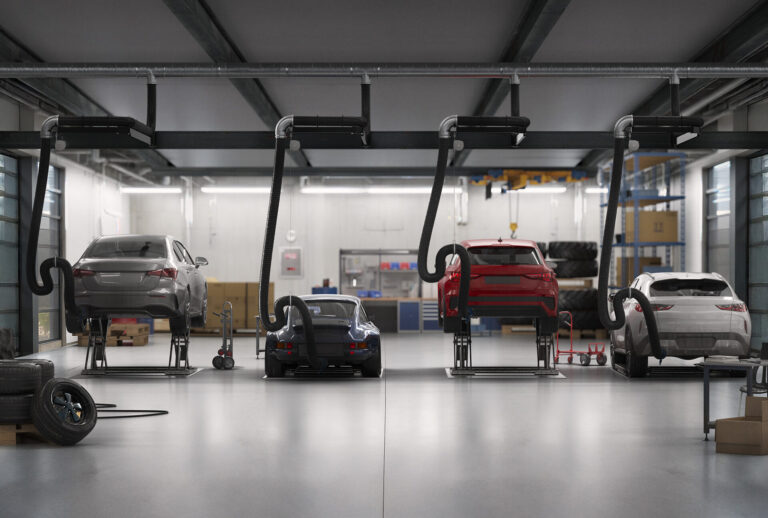
Why local extraction is essential for vehicle exhaust and welding fumes
Welcome to the open house on Saturday, November 9

Jussi Minkkinen is Fumex’s new Production Manager – “I am driven by continuous improvement”

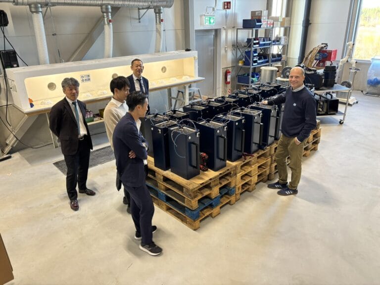
Japanese Dalton visits Fumex – focus on future cooperation
Introducing Mike Murphy – Movex’s new National Sales Manager

Opening ceremony for our new headquarters – See the pictures from the event!

Introducing Kenny Stenberg – ISO Coordinator at our parent company Fumex

Increasing the knowledge of environmental and social sustainability

Anders Hedlund takes the floor – “Trust me, there is a lot going on at Movex!”
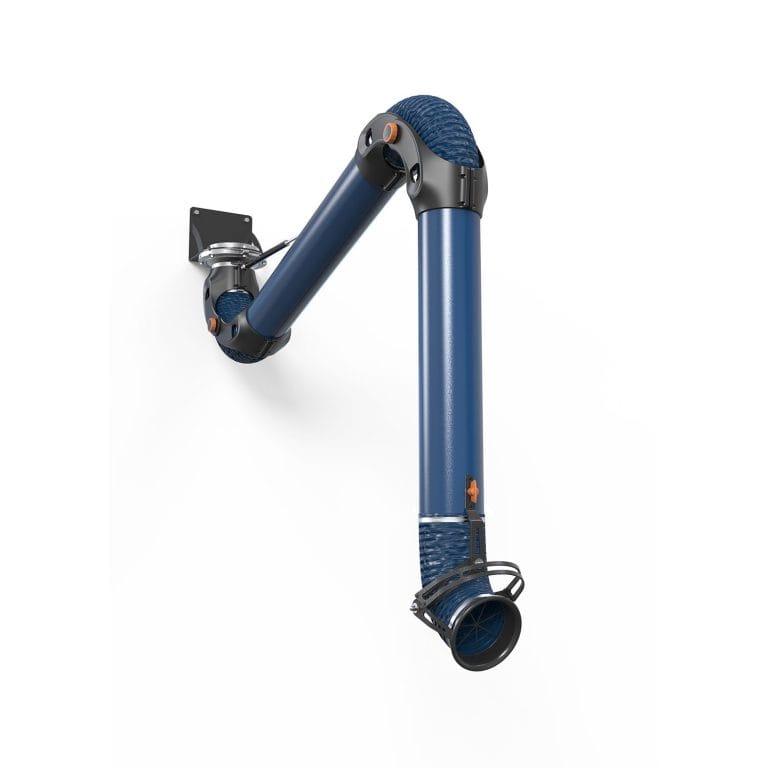
PRX – An effective “heavy duty” extraction arm
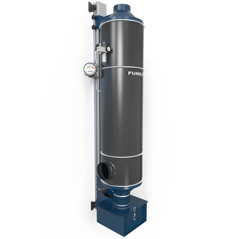
CV – Modular filter for both particles and gas
5 Common Design Mistakes in Laboratory Extraction Systems
Laboratory extraction systems are often designed around individually good components: a suitable extraction arm, correctly selected fan and properly sized accessories. But those components still need to work together.
An extraction arm that cannot comfortably reach the source, a restrictive duct layout or an unbalanced multi-point system can all reduce performance once the installation is in use.
Here are five common design mistakes to consider when planning a laboratory extraction system.

1. Choosing the mounting position before considering the work
One of the simplest mistakes is deciding where the extraction arm will be installed based primarily on the room layout.
There may be a convenient ceiling connection directly above the bench or an open section of wall next to the workstation. But that does not necessarily mean it is the right position for the extraction arm.
The important question is:
Can the hood comfortably reach every location where contaminants will actually be generated?
The arm should be able to follow the work without being permanently operated at its maximum reach or interfering with instruments, lighting or the user.
Our ME series is available with ceiling, wall and table mounting options for this reason. The product range also includes multiple arm lengths so the mounting position can be matched to the work area.
For ME, we also provide recommended mounting heights and side displacement relative to the work area to help optimize reach.
2. Positioning the extraction point on the wrong side of the process
Reach is only one part of positioning. The hood also needs to be positioned so contaminated air travels away from the user.
If the user’s head is located between the emission source and the extraction point, the system can draw contaminants through the breathing zone before they are captured.
OSHA’s local exhaust guidance specifically recommends positioning hoods so contaminants are not drawn through the worker’s breathing zone. It also emphasizes that capture hoods need to be located close to the contaminant source.
Think about the layout as three positions:
User → Source → Extraction point
Where practical, the extraction path should continue away from the user rather than crossing the user’s breathing zone.
This should be considered while the workstation is being designed, not after the extraction arm has already been mounted.
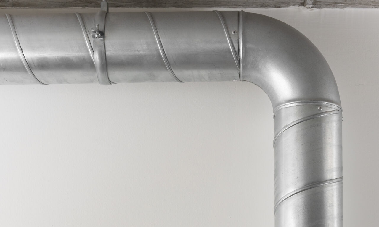
3. Using ductwork that creates unnecessary resistance
Once the contaminant enters the extraction arm, it still has to travel through the duct system.
Duct diameter has a significant effect on resistance.
For a given airflow, reducing the duct diameter increases air velocity and friction loss. The U.S. Department of Energy notes that duct friction represents a significant part of the energy demand in many fan systems and that increasing duct diameter can substantially reduce friction losses.
That does not mean the largest possible duct is always the correct choice.
Duct sizing also has to consider the contaminant being transported, required air velocity, available space and the rest of the system.
For processes carrying particles, sufficient transport velocity may also be necessary to reduce settling in the duct. OSHA defines minimum transport velocity as the velocity needed to transport particles with little settling.
The objective is therefore not simply: Bigger duct = better.
It is: Choose the duct size that provides the required airflow without creating unnecessary resistance.
4. Adding too many bends — especially around the fan
Real laboratories rarely allow perfectly straight duct runs.
Columns, suspended ceilings, utilities and other building systems often require the ductwork to change direction.
Every additional fitting affects the system. But the location of those fittings can matter just as much as the number of them.
Bends and transitions can create turbulence and additional pressure losses. Poor airflow conditions immediately before or after the fan can have an even greater effect.
AMCA refers to these installation-related losses as system effect. Elbows, dampers and other obstructions placed too close to a fan inlet or outlet can produce nonuniform airflow, reducing fan performance and potentially increasing noise, vibration and energy use.
The U.S. Department of Energy likewise notes that ductwork that is bent or shifted during installation can create nonuniform airflow around the fan and lead to performance problems.
This does not mean every bend is a design error. It means bends should have a reason to be there.
A simpler duct route generally gives the designer fewer losses to overcome and makes the final system easier to predict.
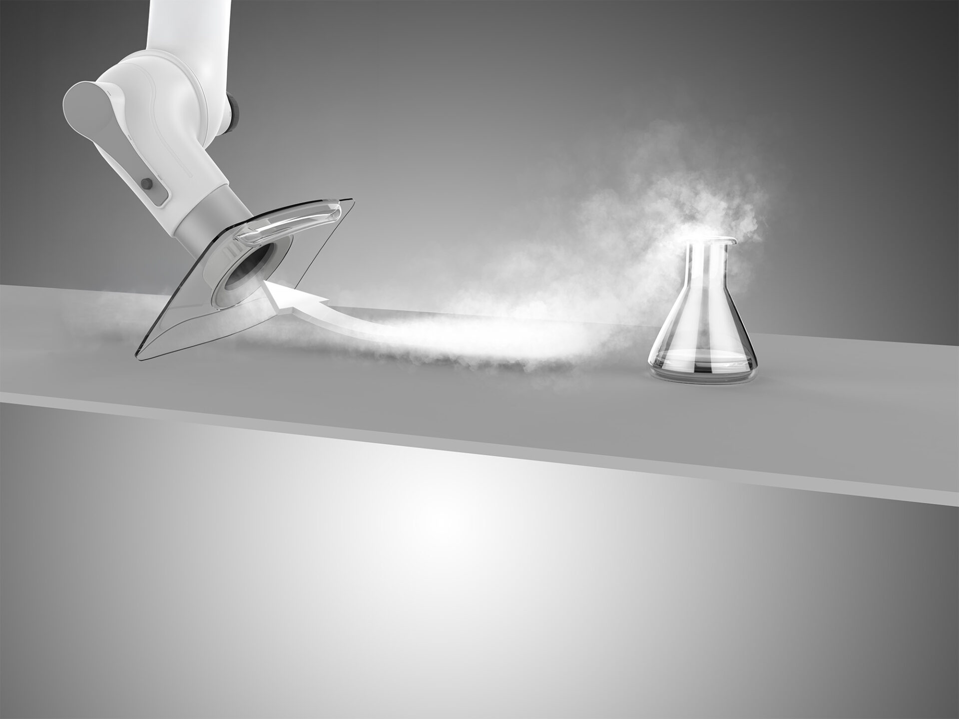
5. Assuming every extraction point will automatically receive the right airflow
This becomes especially important when multiple extraction arms share one fan. Imagine several branches connected to the same main duct.
One branch is short and direct. Another is longer and includes several fittings. Without proper system design and adjustment, those two branches will not necessarily behave in the same way.
Air follows the path of least resistance. A branch with too little resistance can receive more airflow while another extraction point receives less than intended.
The Department of Energy notes that a low-resistance branch. For example because a damper is stuck open or a duct has developed a significant leak, can effectively rob airflow from other delivery points.
Dampers can therefore be used to adjust resistance and control airflow in individual branches.
For laboratory systems with several extraction points, this makes balancing an important part of commissioning.
The objective is not necessarily to give every extraction point the same CFM.
It is to make sure each extraction point receives the airflow required for its application.
Variable demand also changes the system
There is another complication in multi-point systems: Not every extraction point will necessarily be operating all the time.
When one branch closes, the pressure conditions in the remaining system change. When several branches open, system demand increases again.
A system designed only around one fixed operating condition may therefore behave differently throughout the day.
For applications like this, our SFC frequency converter can be combined with the ST 300 pressure transmitter. The pressure transmitter monitors duct pressure and the frequency converter can regulate the fan accordingly.
This allows fan operation to respond to changing system conditions rather than treating maximum demand as the only operating condition.
The principle is also supported by U.S. Department of Energy fan-system guidance, which describes variable-frequency drives as a way to adjust fan output to changing system requirements.
A sixth mistake: installing the system and never checking the result
Design calculations are important. But the installed system should also be verified.
The actual duct route may differ slightly from the drawing. Dampers may require adjustment. Other building ventilation can influence the workstation. And the system may not behave exactly as predicted once every branch is operating.
OSHA’s technical guidance recommends documenting ventilation-system operation and taking physical measurements such as hood velocities, duct velocities and static pressure when evaluating system performance.
For a new laboratory system, this gives you something particularly valuable: a baseline.
If airflow or extraction performance changes later, there is a known operating condition to compare against.
This can help distinguish between a process change and problems such as:
- A damper that has moved
- A blocked duct
- A loaded filter
- A fan issue
- A modification elsewhere in the system
OSHA also identifies clogged ductwork, closed dampers and clogged air-cleaning devices among potential causes of poor ventilation performance.
Good installation starts before anything is mounted
Many ventilation problems are easier to prevent on a drawing than to correct after installation.
Before choosing the mounting point, look at the actual working area.
Before routing the duct, consider the resistance each bend and transition will create.
Before selecting the fan, calculate the airflow and pressure requirements of the complete system.
And when multiple extraction points are connected together, consider how the system will behave both at full demand and when only part of the laboratory is in use.
Good source extraction is not created by one component.
It comes from designing the extraction arm, ductwork, dampers, fan and controls as one system.
Need help planning your laboratory extraction system?
Tell us about your workstations and number of extraction points. We can help recommend Movex extraction solution before installation.